- Academy
Fundamentals of Coarse Wavelength Division Multiplexing
what is CWDM? Coarse Wavelength Division Multiplexing is a variation of Wavelength Division Multiplexing (WDM) technology, used to transmit multiple optical signals through a single fiber. Unlike Dense WDM (DWDM), CWDM employs wider spacing between wavelengths, making the equipment less complex and more cost-effective. It allows for up to 18 channels in specific transmission windows of silicon optical fibers, enabling efficient and scalable data transfer in optical networks.

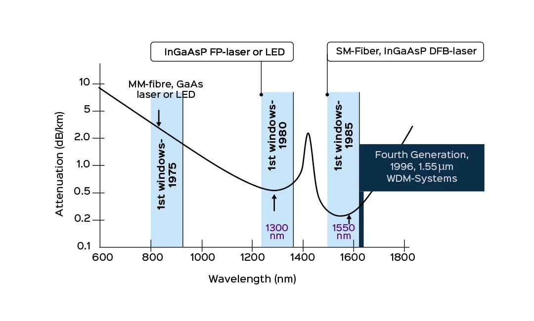
Figure 1: Wavelength windows in optical communication
Understanding the Basics of WDM: CWDM vs. DWDM
WDM technology has three primary variations: conventional WDM, CWDM, and DWDM. While they all share the basic principle of using multiple wavelengths of light on a single fiber, they differ in wavelength spacing, the number of channels, and their ability to amplify multiplexed signals. For example, CWDM uses wider channel spacing, making it suitable for shorter-range urban applications, whereas DWDM is ideal for long-distance communication with dense channel spacing.
CWDM Transmission Windows and Optical Fiber Communication
CWDM operates across multiple transmission windows in optical fibers, particularly the 850 nm, 1310 nm, and 1550 nm windows. These windows are crucial because they define the range of wavelengths that an optical fiber can efficiently transmit with minimal attenuation. In CWDM, both the second (1310 nm) and third (1550 nm) windows are utilized, along with certain frequencies where OH scattering may occur. To maximize performance, OH-free silica fibers are often recommended for Coarse Wavelength Division Multiplexing systems.
Development of Optical Fiber Windows and Their Importance
The concept of transmission windows emerged as optical fiber technology developed. In the 1970s, the first optical communication systems operated in the 850 nm range using multimode fibers. As technology evolved, the second window (1310 nm) was introduced, reducing the need for costly amplifiers. The third window (1550 nm), with its lower attenuation, became the foundation for high-speed DWDM systems. These transmission windows helped standardize the manufacturing of optical equipment, improving the efficiency of fiber communication.
CWDM Technology: Simplifying Fiber Communication
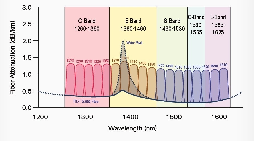
CWDM simplifies the design of transceivers by increasing the spacing between wavelengths, making the overall system cheaper to deploy. It utilizes a broad spectrum, spanning both the second and third transmission windows, enabling 18 channels over a single fiber. Modern CWDM systems often use OS2 fibers, which conform to ITU-T G652.D standards. These fibers eliminate the “water peak” attenuation at 1383 nm, allowing for the full use of all available channels in urban networks.
ITU-T Standards for CWDM: G.694.1 and G.694.2
The International Telecommunication Union (ITU) has established separate standards for DWDM and CWDM applications. The ITU-T G.694.1 standard, issued in 2002, defines frequency sets for DWDM, while G.694.2, introduced in 2003, focuses on wavelength sets for CWDM. The wavelengths for CWDM range from 1270 nm to 1610 nm, divided into different optical communication bands, including the O, E, S, C, and L bands.

Figure 2: Wavelengths set diagram according to ITU-T G.694.2 standard for propagation in G.652 optical fiber
Wavelength Bands Used in CWDM
CWDM operates across multiple wavelength bands, each with specific uses:
- O-Band (1260 nm – 1360 nm)
- E-Band (1360 nm – 1460 nm)
- S-Band (1460 nm – 1530 nm)
- C-Band (1530 nm – 1565 nm)
- L-Band (1565 nm – 1625 nm)
These bands are utilized to accommodate different optical communication needs, with the C-Band and L-Band being particularly significant for high-capacity data transmission.
Read also :
Video SFP Transceivers
Application of Coarse Multiplexing
This technology is used in telecommunication networks and urban Ethernet and cable TV networks. Some small form factor pluggable (SFP) transceivers have standardized wavelengths, and there is a wide range of such SFPs with various bit rates for a variety of SDH/OTN telecommunication signals, Ethernet signals, and video signals. For example, for HD-SDI, SD-SDI, 3G-SDI, and 12G-SDI digital video signals, SFP modules with these lasers are available.

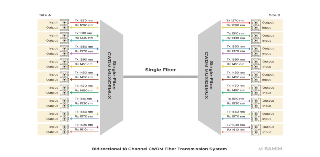
Figure 3 shows the two-way communication of SFP sets that are in the form of optical transceivers in various systems, including Ethernet switches or converters (optical to electrical and electrical to optical) of video transmission systems. In this link, each system performs multiplexing and De-multiplexing simultaneously. There are nine SFP transceivers with coarse lasers on each side, each of which sends an optical signal with a specific wavelength from its transmitter port and through the system by optical fiber to the opposite system. On the other hand, SFPs receive signals sent from SFPs on the other side from the same path by the coarse system from their receiver port. Therefore, nine different wavelengths in one direction and nine different wavelengths in the opposite direction and a total of 18 wavelengths are established through one optical fiber and two systems.
Samim CWDM mux
Samim OMD-1800, functioning as a CWDM optical mux and demux, is a passive bidirectional optical broadcast multiplexer and de-multiplexer. It allows multiple optical signals at various wavelengths to travel through a single optical fiber link. It can combine up to 18 different wavelengths from separate optical fibers into one optical fiber, while also separating up to 18 different wavelength signals from a single optical fiber into 18 individual optical fibers.


