
- Academy
Synchronization and Timing in Video Broadcast
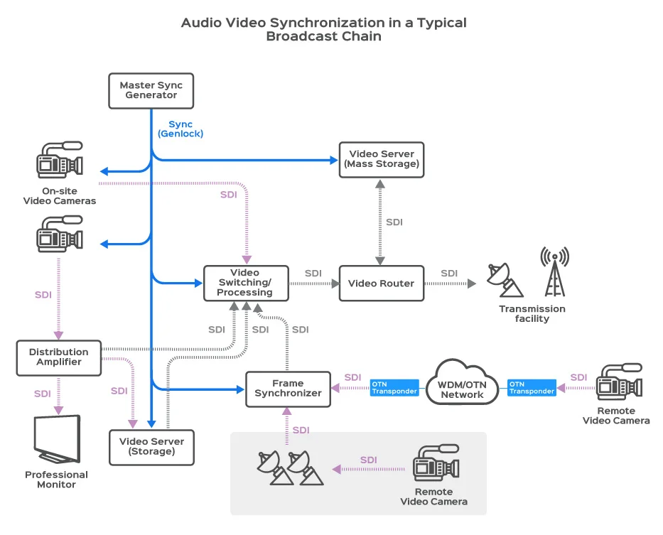
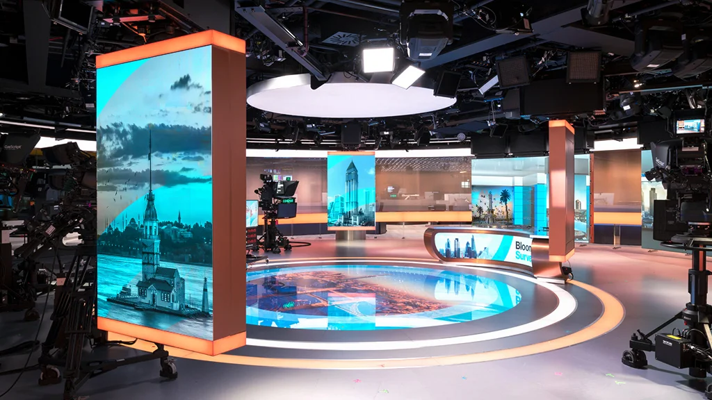
Audio video synchronization is essential for seamless switching between sources, especially in live production studios with multiple cameras that are capturing dynamic content.
A master synchronization generator distributes a sync signal to all video sources, allowing video-switching equipment to effortlessly select between them without buffering or re-syncing. In broadcast studios, synchronizing all equipment to the same clock is crucial for maintaining video quality and avoiding frame loss.
Let’s explore the key components of a broadcast video system and their role in the synchronization process.
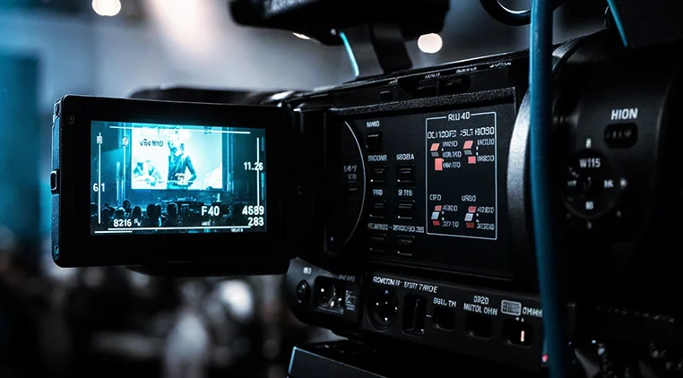
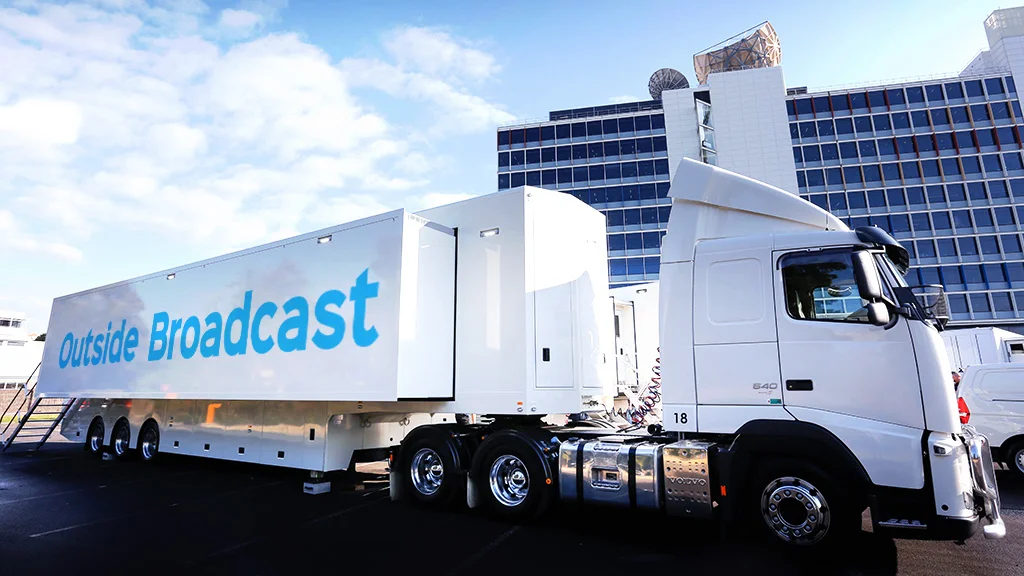
Typical example of a professional video broadcasting
Importance of synchronization in broadcast video
audio video synchronization is essential for maintaining seamless and accurate timing across multiple cameras, audio recording and distribution devices, and AV signal processing equipment. Without proper synchronization, issues such as frame misalignment, lip-sync errors, and glitches during transitions can occur, affecting the overall broadcast quality. Synchronization ensures that all video and audio signals are perfectly aligned, providing a smooth and professional viewing experience.
Synchronization of Professional Video Cameras
In professional broadcast cameras, synchronization is crucial to ensure soft switching between cameras. Sync pulses and sampling clocks of video processors, as well as SD/HD-SDI clocks, need to be synchronized via genlock with other equipment in the studio. The video clock requires low jitter, as any jitter affects the A/D converter’s performance. Additionally, the audio clock must synchronize with the video clock since digital audio is embedded into the SD/HD-SDI stream. Professional broadcast cameras, such as television studio cameras, rely on these synchronized processes to maintain high-quality video and audio output.
Genlocking , Synchronization of video equipment
In a production studio with multiple cameras, synchronizing all video sources is essential for smoother downstream processes such as switching, editing, keying, and fading. This process, called genlocking, ensures that all video sources are aligned to a common synchronization signal. A master sync generator supplies this reference signal to all the equipment that are generating audio or video streams. In professional studios, the standard signal used for genlocking is called a black burst or color black, which is an analog composite video signal without actual video content.
A sync separator extracts the timing portion of the composite video signal, discarding the unnecessary parts. This timing portion is then synchronized with a timing generator. The horizontal sync pulse (HSYNC) is typically used as a timing reference due to its consistent and precise frequency. The timing generator locks onto the HSYNC signal, removes any jitter, and generates the video sampling clock.
Frame Synchronizer
At times, an asynchronous video signal must be synchronized with the studio’s genlocked reference; e.g., when a remote camera sends a video signal that does not have access to the studio’s master genlock. In such cases, a frame synchronizer is used to buffer and retime the unsynchronized signal to match the master synchronization source.
This process generates a synchronized (genlocked) copy of the video, ensuring genlock sync for use by other studio equipment. Synchronizing the video involves buffering each frame and re-transmitting it using the studio’s genlock clock reference. The video is deserialized into its parallel 10-bit or 20-bit YCbCr component format, buffered, and re- clocked with the genlock signal. Finally, the parallel YCbCr video is serialized and sent through a cable driver, producing a genlocked SDI video signal that is in sync with the rest of the studio’s equipment.
The SDI re-clocker eliminates alignment jitter from SDI data stream by using phase-locked loop circuitry. This process typically requires an external reference, such as a crystal oscillator (XO) or a voltage-controlled oscillator (VCXO). Cable drivers are then employed to buffer the video signal and distribute it to multiple destinations.
Video synchronization in Distribution Amplifier modules
Broadcast studios often use multiple audio video signal sources for the production and some of these signals need to reach long distances. Distribution amplifiers are used to help extend the distance that the video signal can reach or to distribute a video signal to multiple destinations.
Distribution amplifiers utilize a cable equalizer to offset the natural low-pass characteristics of coaxial cables used for carrying SDI video signals. The cable equalizer significantly extends the range of the SDI cables to over 140 meters for HD signals and 300 meters for SD signals.
More than one SDI distribution amplifier can be used in the signal path to further extend its reach, but they should be used sparingly to maintain the best possible signal integrity. One of the issues with using long cables and multiple distribution amplifiers is jitter accumulation in the video signal.
synchronization in Video Switchers
Production Video switchers (also called Vision Mixers) are used to select one out of several available video sources. This is where an operator monitors multiple video sources and switches between them to produce the final production video signal. Switching between video signals is not a trivial task, and without synchronization (or genlocking) it would be almost impossible. Before switching between two or more video sources, the individual video signals must be de-serialized, reconstructed frame-by-frame, and buffered.
Precise alignment between video frames is necessary when combining video from different sources. Genlocking the video sources reduces the amount of buffering needed to keep the video frames aligned and ready for switching. After the video has been combined, it is serialized and retimed to the master sync generator so that the video that it produces is synchronous with the rest of the studio’s equipment.
synchronization in Video Servers
The purpose of video server is to store captured video signal for playback and later post processing. Producing the final video stream requires mixing of live and pre-recorded material. The video server allows storage of live video so that it can be transmitted at a later time or mixed-in with live video from another source. The SDI video signal is usually stored in a compressed digital form after going through equalization, jitter clean-up, and de-serialization. The process is reversed when the video is retrieved.
It is obvious that Video Server needs to be synchronized to the other equipment in the studio to prevent data loss. Since audio video synchronization is lost during storage, it must be re-synchronized to the studio’s master sync generator before moving on to downstream equipment.
Read also :
Delay Compensation in Broadcast Production
Jitter Requirements for Video Clocks
As the video signal travels through the interconnecting wires and the components that make up the video network, the digitized signal will accumulate jitter. If it becomes excessive, the video signal will deteriorate to the point where it is no longer usable or recoverable. For this reason, jitter reduction circuitry is included at several points throughout the video path to maintain signal integrity.
The process of recovering video from the SDI signal requires extracting both the data and a sampling clock from the data stream. This is known as clock and data recovery (CDR). Since the clock is recovered from the SDI data stream itself, it will track its jitter but only within the loop bandwidth of the phase-locked loop (PLL) based CDR circuitry.
Jitter that occurs above this loop bandwidth will not be tracked; it will be filtered. Although recovering a filtered clock sounds like a good idea, it can cause decoding errors if there is still excessive jitter on the data. For this reason, SMPTE has specified limits on the jitter content of SDI signals. SMPTE defines two types of jitters: timing and alignment. Timing jitter covers the entire frequency spectrum starting at 10 Hz. Alignment jitter focuses on the frequency spectrum that CDR circuits cannot track. Therefore, alignment jitter has a much more powerful impact on system performance and as a result has tighter limits.
We have seen that synchronization plays a critical role in the broadcast studio. Not only is it necessary within the video signal itself so that the receiver knows how to frame the pictures that it receives, but it is also necessary at the physical level to ensure proper serialization and de-serialization of the video signal.
The oscillators and phase locked loops that make synchronization possible in above-mentioned video systems need to provide multiple frequencies to support today’s variety of standard definition and high definition resolutions. Not only is flexible frequency conversion important, but controlling jitter with properly placed jitter filters is critical in successful recovery of the video signal as it propagates through the video equipment within a studio.
- Article
Live Sports Production Workflow Explained: Tools & Tips
Live sports broadcasting is one of the most demanding and fast-paced types of production in the media industry. It requires careful planning, advanced technology, and a skilled team to pull…
- Article
What Really Powers a Successful Live Broadcast production? Key Components Uncovered
A successful live broadcast hinges on a combination of advanced technical infrastructure, skilled human resources, thorough planning, and reliable equipment. This research delves into the vital elements that underpin successful…
- Article
Building a Future-Proof News Broadcast Studio: Key Components and Best Practices
The rapid evolution of technology and changing viewer expectations require news broadcast studios to be adaptable, scalable, and resilient. This research explores the essential components and best practices for designing…
- Article
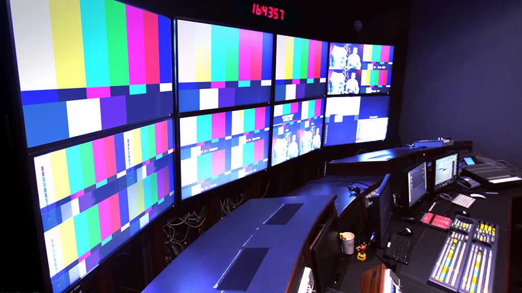
Why Color Bars Remain Essential in Modern Digital Broadcast System
Color bars remain essential in modern digital broadcast systems because they serve as a universal reference standard for image quality, calibration, and troubleshooting. They help ensure consistent color reproduction, luminance,…

- Article
TV Headend Equipment Explained: Applications & Key Benefits
The digital headend in TV broadcasting serves as the central hub for aggregating, processing, and distributing television signals to subscribers. Its evolution from analog to digital systems has significantly enhanced…
- Article
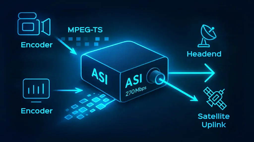
ASI in Broadcast Transport Streams: The Backbone of Digital TV Signal Distribution
Asynchronous Serial Interface (ASI) signals are pivotal in distributing digital television signals, especially within the broadcast infrastructure. This article examines the critical role of ASI in broadcast transport streams, highlighting its…
- Academy
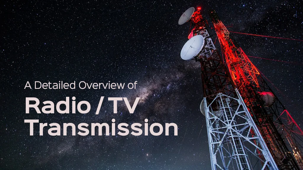
A Detailed Overview of TV Transmission Sites
In an era where broadcast media remains a dominant force in information dissemination, understanding the essential equipment for TV transmission sites is crucial. This guide provides a comprehensive overview of…
- Article
- Academy
Taking Your Broadcast Outside: Essential Considerations and Pro Tips
Outside broadcasting (OB) encompasses various challenges and opportunities that media professionals face when delivering live content in diverse outdoor environments. This blog explores the essential considerations necessary for successful OB,…

- Academy
Fiber Optic Multiplexers Explained: How They Improved AV Signal Transmission
Fiber optic multiplexers are simple but advanced devices that have transformed how audio-video (AV) signals are transmitted, offering unparalleled advantages in terms of bandwidth, signal quality, and efficiency. This article…
- Academy
TV Broadcast Standards: How They Revolutionized Television
From the earliest days of television in the 20th century, TV broadcast standards have served as a fundamental driving force in the development, evolution, and global influence of this medium….